A ship with more office requirements will mechanically require larger amounts of fuel for each run of ocean trip, resulting in a rise in fuel expenses for the owner. besides, according to the holocene trends, the overall efficiency of a embark is quantified by Energy Efficiency Design Index ( EEDI ). The lesser the EEDI of a ship, more is the efficiency of the ship from an environmental and social point of view. As the EEDI of a transport being proportional to the world power required, it is constantly preferred by the designers to reduce the might requirements of a embark by every way potential. It reduces the EEDI, and in turn, brings down the carbon footprint of the transport .
Before we go into the core subject of this article, let me tell you what this article is about. In this article, we will first look at the ways of determining the power requirements for Marine Diesel Engines and Diesel Electric Propulsion Systems ( note that the methods of estimating the exponent ratings for both the systems are quite different from each other ). however different they may be, the first step is always the same, careless of the type of propulsion system that is to be used by the ship, as discussed below .
The First Step: Calculate the Resistance of a Ship
In order to calculate the resistance of a transport, the first footprint is to conduct a tow tank test. In case of new hullforms, a tow tank car test is preferred. however, if the hullform of the ship in invention has already been tested in a tank, it is preferred to equitable follow the scaling method acting ( Which we shall discuss soon ).
In a tow tank test, the resistor of the exemplar scale is obtained in the computer of the carriage. This is then scaled up to the transport ’ s scale by using a set of steps recommended by International Towing Tank Conference ( ITTC ) .
The tow tank however gives on the bare hull resistance of the ship. Air Resistance, Resistance due to Appendages and a Correlation Allowance are added to obtain the full electric resistance of the embark. This sum electric resistance when multiplied with the ship ’ s speed gives the effective Power of the embark ( PE ) .
An concern tip : If you now rate the transport ’ south engines to the obtained effective power, the ship should move at the design speed. Right ? But if you actually did, the transport would only be able to operate at a rush lower than this. We will discuss the reason as we proceed .
The Second Step: Decide on the Type of Ship Propulsion System
This is one of the most decide steps of the integral process. excerpt of the wrong type of propulsion arrangement may result in an economic calamity for the transport in future. Years of experience and inquiry has now provided us with a clear idea as to what kind of propulsion should be preferred on different kind of ships .
Diesel-Mechanical Propulsion is preferred in most cargo ships which require low amphetamine operations and lower function costs ( process costs for Heavy Fuel Oil used in Marine Diesel Engines is lesser than operate costs of Diesel Electric Propulsion Systems ). In the recent times, decelerate steam has become an efficient method to counter the effects of the nautical recession, and diesel propulsion is hence preferred in most cargo ships ( bulk carriers, oil tankers, container ships ) .
Diesel Electric Propulsion is preferred in ships which require more electric might ( for case cruise ships require more electric power to run its facilities, drillships that require moral force aligning systems for most of the fourth dimension of operation, etc. ) and ships that want undisturbed operations with vary torsion ( for example, tug ). This is one of the most luminary advantage of diesel electric propulsion. Where diesel mechanical propulsion systems do not offer high efficiencies at all torques, diesel electric propulsion systems can operate at high efficiencies at about all torsion variations .
 In the above graph, it is apparent that the torsion supplied by the Engine ( diesel engine ) varies with rush. That is, higher torsion can entirely be obtained at higher engage speeds. But if higher torques ( of propeller ) are required at lower speeds ( which is the case of tugs and moral force positioning systems ), an electric drive ( which is used in diesel electric propulsion systems ) stands out .
The Third Step: Estimate the Engine or Diesel Alternator Ratings
For Diesel Mechanical Propulsion:
Remember the interview we had raised in the gratuity above ? Why would the embark not operate at design rush if we rated the engines at the effective office ?
> The underground calculated from the towing tank tests is only the unsheathed hull resistance, that is, the effect of the propeller is not considered in the above. Whereas, when a propeller operates behind the ship, there is the following we must consider here :
electric resistance of the embark increases from the value calculated in publicize hull condition. The propeller must operate at a torsion that is sufficient to overcome this augment in resistor and besides enable the ship to overcome its bare hull resistance .
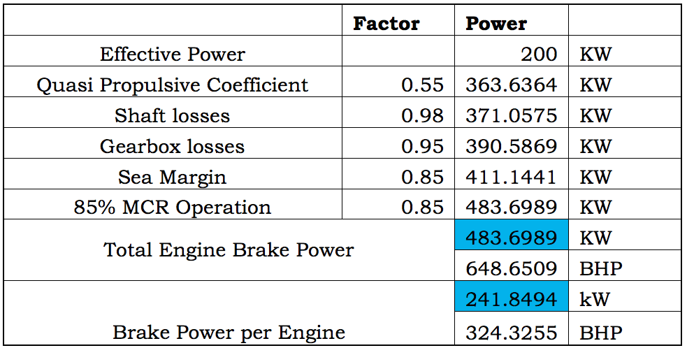
Hence, due to the losses in the propeller, the power delivered to the propeller ( PD ) at the shaft output should be more than the effective power ( PE ). The ratio of the effective might to the deliver office is called Quasi Propulsive Coefficient ( QPC ). QPC normally ranges from 0.55 to 0.65 .
> The office at the engine output ( i.e. shaft input ) is not in full obtained at the spear end product. This is because of the frictional and estrus losses that occur along the length of the quill. These are termed as cock losses. shaft losses are normally taken as 2 percentage .
> In sheath of smaller ships where high revolutions per minute engines are by and large used, reduction gearboxes are used to reduce the spear revolutions per minute, or operated at respective RPMs. The losses induced by the gearbox are classified under gearbox losses. Gearbox losses range from 4 to 5 percentage .
> The immunity estimated during the design phase does not consider the effect of waves. Due to the action of waves, the actual immunity on a transport is higher than that in sedate water system conditions. Hence, a margin of 15 percentage is considered as sea margin, and the engine world power is rated then that it overcomes the sea allowance .
> It is always desirable to keep specific fuel anoint consumption arsenic low as possible. For marine diesel engines, the Specific Fuel Oil Consumption ( SFOC ) is minimum when the RPM of the engine is corresponding to 85 % of utmost continuous military rank ( MCR ). Which means, that the design focal ratio should be attained, not at the rated MCR but at 85 % of the MCR. so to obtain the MCR, the represent factor of 0.85 is considered .
The following board shows a calculation that is used to obtain the rated locomotive office from the effective power of twin-engine embark using the above factors :
Read more: What is the Maritime Industry?
 For Diesel-Electric Propulsion:
I will discuss the basic components of a diesel electric propulsion equitable to an extent that makes is potential for a proofreader at a preliminary stage to understand what we will be discussing on the appraisal of baron evaluation of a diesel electric propulsion system .
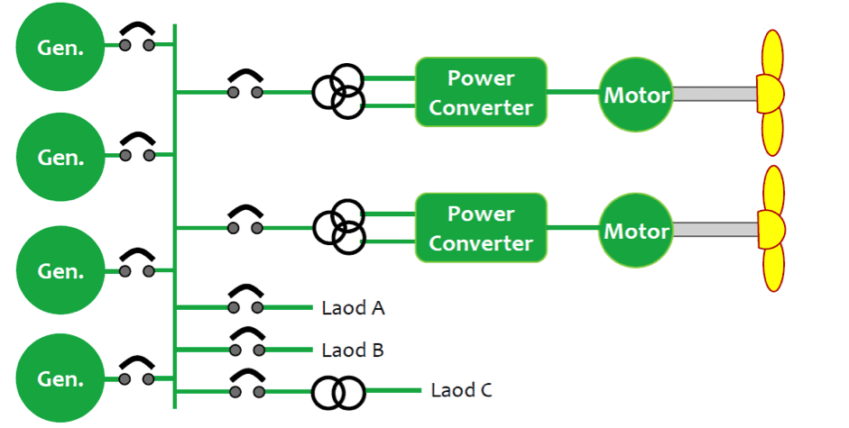
The basic components of a diesel electric propulsion system are :
Diesel Generators, Transformers, Electric Motors and Loads. now, the loads on the system may be a electric drive driven propulsion pod, or a bow pusher, or any component of hotel load ( lighting, HVAC, etc. )
 In this case, the electric propulsion motors, propellers and other loads together form the load of the entire office plant. But it is to be considered that not all loads will be in operation in every stipulate. For case ,
In harbor, the propulsion loads will be absent, whereas the hotel loads will be present .
In case of Dynamic Positioning Operations, both hotel loads and propulsion units will be in operation. then in this case, the load on the diesel generators will be maximal .
therefore, we will basically need to calculate the total ability prerequisite before deciding upon the number of diesel generators required to meet all the conditions. Once the total might is decided, the number of diesel generators will be decided upon based on certain principles that we shall discuss late on .
inaugural, in club to calculate the entire exponent necessity, designers prepare a Load Chart which lists out all the electric loads on the ship. And the load graph is disposed, taking into retainer three operating conditions in general :
Sailing, Harbour and Maneuvering.
In the load chart, the might requirements of each electric lode on the ship is calculated by multiplying the Maximum Rated Power of the part with two factors :
Load Factor: It is the proportion of the operating exponent to the maximum world power military rank of the part .
Utility Factor: It is a factor which determines the extent of operation of the particular component in a especial condition .
For exercise, for a steer gearing equipment :
 notice that the utility gene is 0.8 in Sailing and Maneuvering Conditions, but 0 in Harbour condition, since in harbour condition the steer gearing is not used. So the contribution of the steering gear equipment to the full power necessity in Sailing Condition will be zero .
In the exchangeable manner as illustrated above, the cargo graph is prepared for all the electrical components on the ship. A sample distribution of the same would look like the watch :
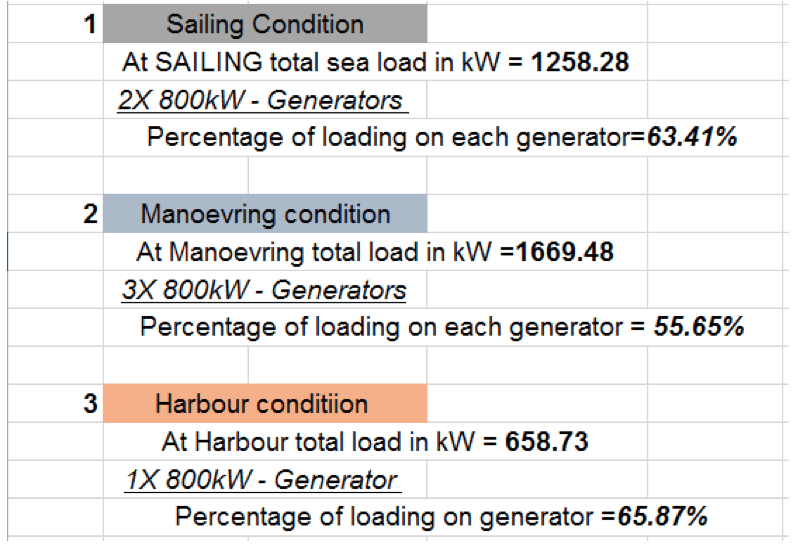
 once the burden graph is prepared, the total baron prerequisite for each of the three conditions ( Sailing, Harbour and Maneuvering ) are calculated by adding up the world power requirement for each component for each of the conditions ( postdate digit 4 ). once this is clear, we will now refer to Figure 4 to understand how the entire number of diesel generators is decided .
 The two rules to be followed in deciding upon the total of generators are :
- If more than one generator is operating in any condition, both the generators should share equal amount of load.
- The load on each generator in any of the three conditions should not be more than 70 percent of the rated power of the generator. (Or, the maximum rating of each generator is decided based upon the condition that seventy percent of the maximum rating is more than the load on the generator in any of the three conditions)
- One additional generator should always be included, which is for standby purpose. Note that this standby generator will not share the load in any of the above three conditions unless any of the working generators are out of order. So the standby generator is not included in the above calculation, but it is usually of the same rating as of the other generators.
This process is iterated by varying exponent ratings and varying number of generators until the above first two conditions are satisfied, and a situation similar to the one in trope 4 is obtained. It is advised that you analyse the first gear two conditions using the above calculate to understand it in beginning hand .


